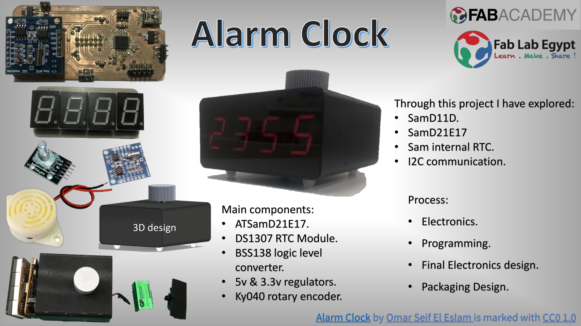
Final Project
Assignment requirements:
- What does it do?
- Who's done what beforehand?
- What did you design?
- What materials and components were used?
- Where did they come from?
- How much did they cost?
- What parts and systems were made?
- What processes were used?
- What questions were answered?
- What worked? What didn't?
- How was it evaluated?
- What are the implications?
Learning outcomes:
- Create your own integrated design
- Demonstrate 2D & 3D modelling capabilities applied to your own designs
- Select and apply appropriate additive and subtractive techniques
- Demonstrate competence in design, fabrication and programming of your own fabbed microcontroller PCB, including an input & output device
Assessment criteria
- Made your slide> 1920 x 1080 pixels with your name, project name, Fab Lab name, a photo/render/sketch of your project, a brief description of what your project is/does
- Made a ~1 minute (10MB/1080p) video of you explaining your project
- Made a separate Final Project page that briefly summarises your project
- Included the BOM (Bill of Materials) for your project
- Linked from this page to any weeks that you worked on your final project
- Linked to your presentation.png and presentation.mp4
- Included all of your original design files in the archive (2D & 3D, board files & code). No external hosting of final project files - discuss file sizes with your instructor
- Included the license you chose
- Acknowledged work done by others
Project Progress
In this page I will be summarizing my final project and writing down steps that if you follow you can make it.
Some people will be more interested to see what mistakes I have done and the process I did before reaching the point where I know what exactly to do, you can go to my Project development week.
Also, to check the project proposal, components and were to buy them and cost ..... etc, you can check my Applications and Implications week.
PCB Design
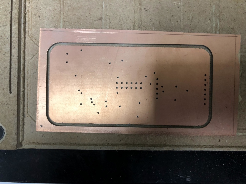
I started with PCB design, as I though that the Enclosure design will depend on the size of the PCB, also, programming and test will be finally tested when there's a PCB.
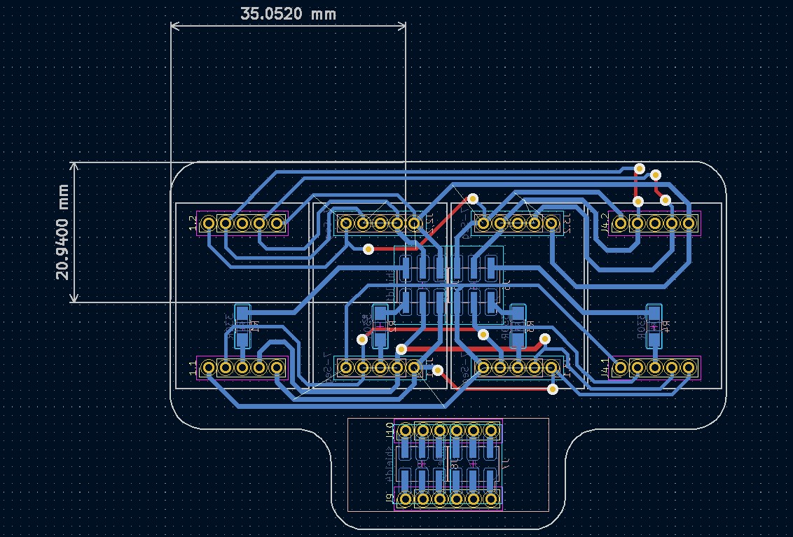
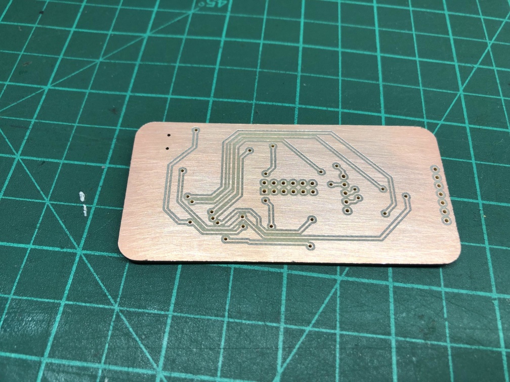
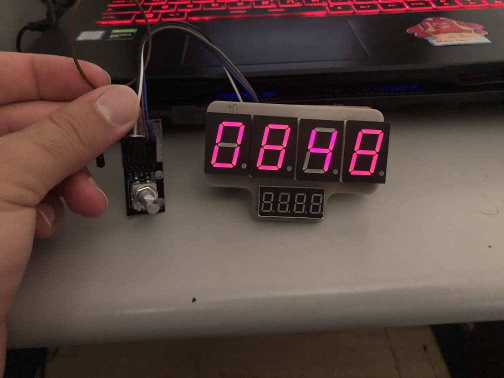
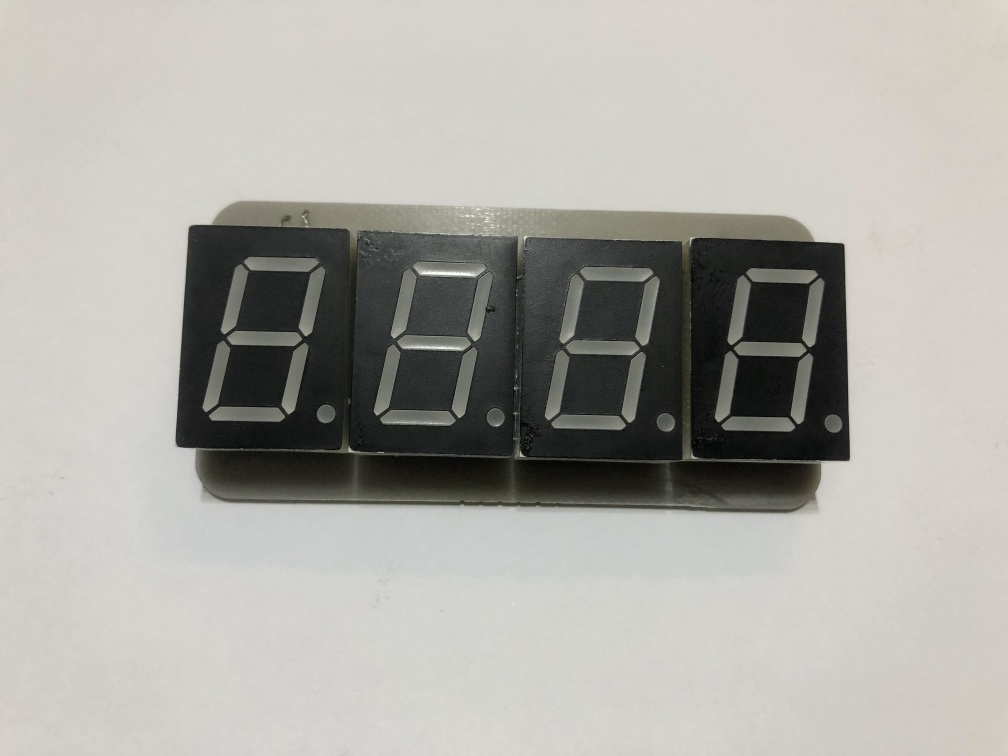
7 Segments PCB
I have changed the Display to 7 Segment as I wanted the clock to have a full screen display of the numbers also, I wanted to have a bigger display of the numbers.
- I used 0.8 inch common anode 7 segment display, 4 of them and made a PCB to have a 4 digit of it.
- The main function of this board is to all segments of the same address (all a together and all b, .... etc), so that we can control the 4 digit with only 11 pins, 7 pins for leds and 4 to control which one will light up.
- later I removed the bottom part, I wanted to display date on it but I didn't have enough pins to control it so I removed it for now.
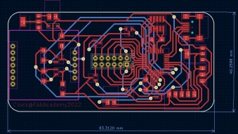
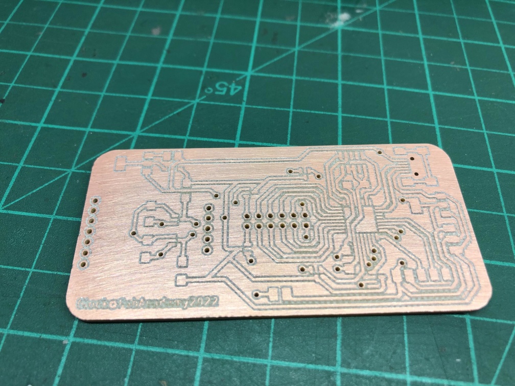
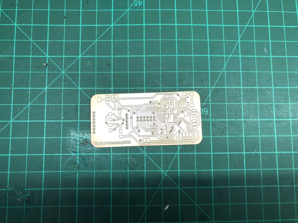
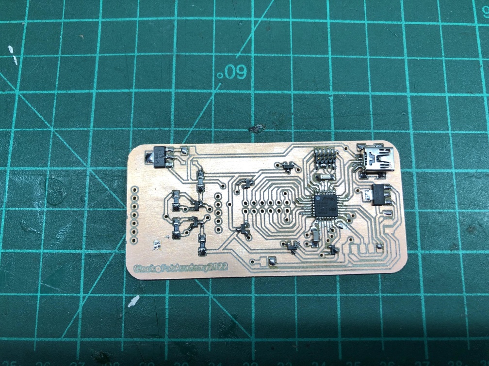
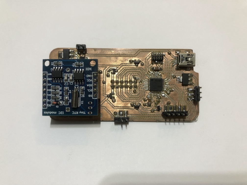
ATSamD21E17
- After a few trials I had an RTC module DS1307 so I used it with logic level converter.
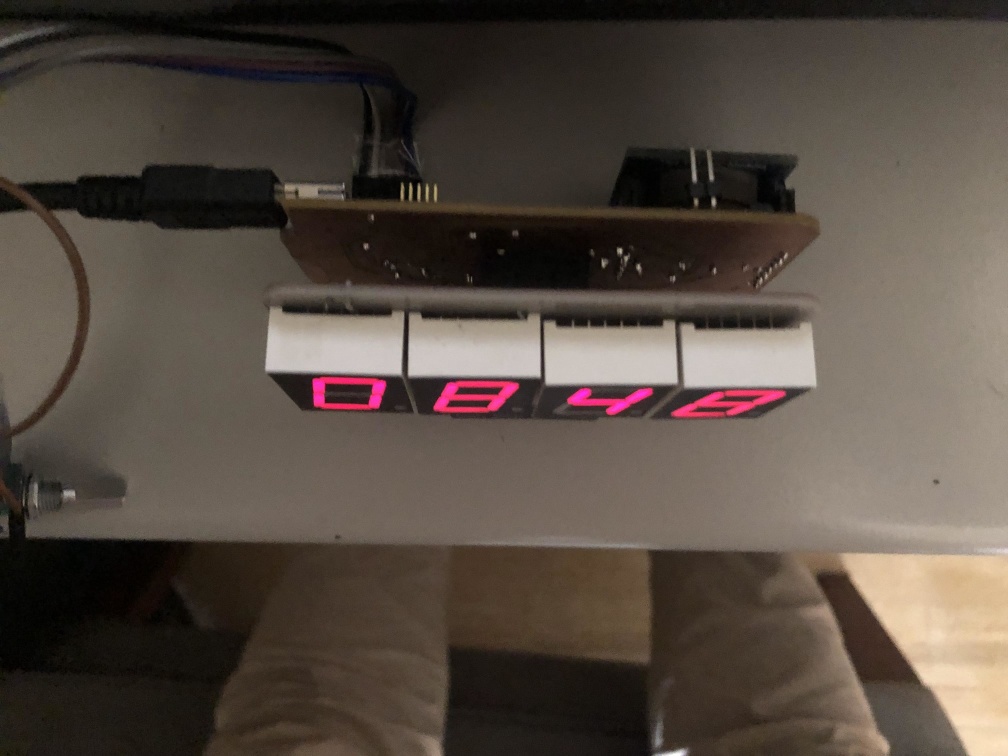
- It worked fine so I went to the PCB design for a full board that has the same outline as the 7 segment PCB to get the minimum size for the clock.
- I managed to place the connector in the middle to connect 2 boards together and make them arlighed and I did it correctly from first time.
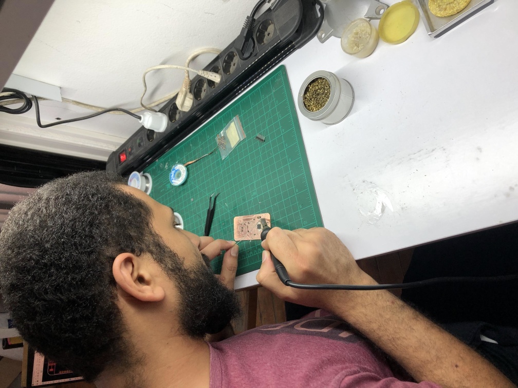
- Design, Manufacturing, soldering, testing and it works, I only removed the 10k resistors that pulls up the logic converter 5V level because the RTC module I used already had a pull up resistors on it.
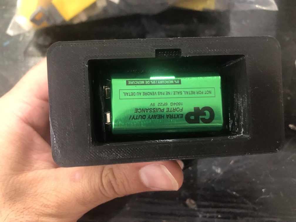
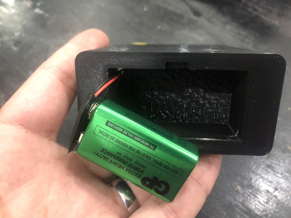
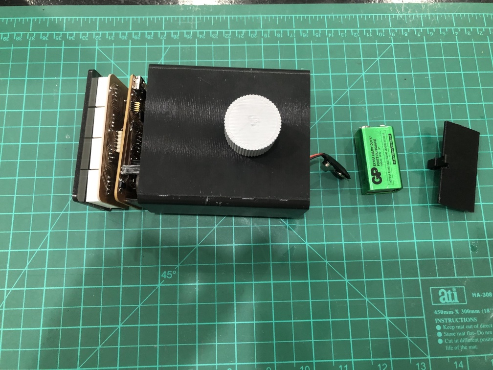
- There's 2 regulators because I wanted to use a 9v battery for power, So 5v regulator for 5v components and 3v regulator for 3v components.
- I placed a diode to the output pin of the 5v regulator because I had a USB that I use to program the board and I was afraid that when using the USB and having the 5v coming from the USB feeded to the 5v regulator while it's not working may damage it so for safety I placed this diode.
Programming
- For programming I had 4 main parts, 1st part is the part that controls the display, 2nd part is the part that reads and updates that time from the RTC, 3rd part is the alarm and the last part is the rotart encoder intrupt.
- For 7 Segments display I used "SevSeg.h" liberary it's a good liberary to control a 4 digit seven segment you need to enter the pins you have the 7 segments on and the 4 digit number you want to display.
- The liberary mainly refreshing the display at a high frequency to be able to display the number on the 4 digits at the same time.
- I used "RTClib.h" to set the time of the clock and get the updated time to display.
- I used Interupt to use the rotary encoder to control the display.
- To set the Alarm I used some if and while functions and I'm sure it can be done in a better way but I'm not a good programmer yet.
  // Date and time functions using a DS1307 RTC connected via I2C and Wire lib
  #include "RTClib.h"

  RTC_DS1307 rtc;

  char daysOfTheWeek[7][12] = {"Sunday", "Monday", "Tuesday", "Wednesday", "Thursday", "Friday", "Saturday"};

  //------Electronics-project-hub.com-----//
  #include "SevSeg.h"
  SevSeg Display;
  //const int hrs_btn = 31;
  //const int min_btn = 30;
  //const int ledPin = 2;
  //int Hrs = 12;
  //int Min = 0;
  //int Sec = 0;
  int Time;
  int ledState = LOW;

  // Rotary Encoder Inputs
  #define CLK 19
  #define DT 18
  #define SW 15

  int counter = 0;
  int currentStateCLK;
  int lastStateCLK;
  String currentDir = "";
  int pinState = HIGH;
  int AH1 = 17;
  int AM1 = 23;
  int AH2 = 13;
  int AM2 = 37;
  int alarm1time;
  int alarm2time;
  char sitAlarm[][5] = {"a1--", "a2--"};

  //speaker pin
  #define SPKR 14


  void setup () {
    Serial.begin(9600);
    // Set encoder pins as inputs
    pinMode(CLK, INPUT);
    pinMode(DT, INPUT);
    pinMode(SW, INPUT_PULLUP);
    pinMode(SPKR, OUTPUT);


    if (! rtc.begin()) {
      //Serial.println("Couldn't find RTC");
      //Serial.flush();
      while (1) delay(10);
    }

    if (! rtc.isrunning()) {
      //Serial.println("RTC is NOT running, let's set the time!");
      // When time needs to be set on a new device, or after a power loss, the
      // following line sets the RTC to the date & time this sketch was compiled
      rtc.adjust(DateTime(F(__DATE__), F(__TIME__)));
      // This line sets the RTC with an explicit date & time, for example to set
      // January 21, 2014 at 3am you would call:
      // rtc.adjust(DateTime(2014, 1, 21, 3, 0, 0));
    }

    // When time needs to be re-set on a previously configured device, the
    // following line sets the RTC to the date & time this sketch was compiled
    //rtc.adjust(DateTime(F(__DATE__), F(__TIME__)));
    // This line sets the RTC with an explicit date & time, for example to set
    // January 21, 2014 at 3am you would call:
    // rtc.adjust(DateTime(2014, 1, 21, 3, 0, 0));


    byte numDigits = 4;
    byte digitPins[] = {10, 8, 9, 11};
    byte segmentPins[] = {3, 2, 4, 7, 6, 0, 1, 5};
    bool resistorsOnSegments = true;
    bool updateWithDelays = false;
    byte hardwareConfig = COMMON_ANODE;
    bool leadingZeros = true;
    bool disableDecPoint = true;
    Display.begin(hardwareConfig, numDigits, digitPins, segmentPins, resistorsOnSegments, updateWithDelays, leadingZeros, disableDecPoint);
    Display.setBrightness(100);


    // Read the initial state of CLK
    lastStateCLK = digitalRead(CLK);


    // Call updateEncoder() when any high/low changed seen
    // on interrupt 0 (pin 2), or interrupt 1 (pin 3)
    attachInterrupt(CLK, updateEncoder, CHANGE);
    attachInterrupt(DT, updateEncoder, CHANGE);
    //attachInterrupt(SW, updateEncoder, CHANGE);


  }

  void loop () {

    if (digitalRead(SW) == 0)
    {

      while (digitalRead(SW) == 0)
        Display.blank();

      Serial.println("SW");

      alarmx();

    }

    //out:

    DateTime now = rtc.now();

    int hh = now.hour();
    int mm = now.minute();

    Time = hh * 100 + mm;
    //Serial.println(now.second());
    Display.setNumber(Time);
    Display.refreshDisplay();

    alarm1time = AH1 * 100 + AM1;
    Serial.println(alarm1time);

    alarm2time = AH2 * 100 + AM2;

    if (alarm1time == Time || alarm2time == Time)
      speaker();

    else
      digitalWrite(SPKR, 0);

  }

  void updateEncoder() {
    // Read the current state of CLK
    currentStateCLK = digitalRead(CLK);

    // If last and current state of CLK are different, then pulse occurred
    // React to only 1 state change to avoid double count
    if (currentStateCLK != lastStateCLK  && currentStateCLK == 1) {

      // If the DT state is different than the CLK state then
      // the encoder is rotating CCW so decrement
      if (digitalRead(DT) != currentStateCLK) {
        counter --;
        currentDir = "CCW";
      } else {
        // Encoder is rotating CW so increment
        counter ++;
        currentDir = "CW";
      }

      Serial.print("Direction: ");
      Serial.print(currentDir);
      Serial.print(" | Counter: ");
      Serial.println(counter);
    }

    // Remember last CLK state
    lastStateCLK = currentStateCLK;


  }


  void alarmx() {
    int i;
    counter = 0;
    while (1) {


      //Display.setChars("nn");
      //Display.setSegmentsDigit(2, Am10s);
      //Display.setSegmentsDigit(3, Am1s);
      Display.setChars(sitAlarm[i]);
      Display.refreshDisplay();
      Serial.println(sitAlarm[i]);


      i = counter ;

      if (digitalRead(SW) == 0) {

        while (digitalRead(SW) == 0)
          Display.blank();


        goto swtch;
      }

    }

  swtch:
    switch (i) {
      case 0:
        while (1) {

          Display.setChars("nn");
          Display.refreshDisplay();

          if (digitalRead(SW) == 0) {

            while (digitalRead(SW) == 0)
              Display.blank();

            while (1) {


              //Display.setChars("nn");
              //Display.setSegmentsDigit(2, Am10s);
              //Display.setSegmentsDigit(3, Am1s);
              Display.setNumber(AM1);
              Display.refreshDisplay();
              Serial.println(AM1);


              AM1 = counter ;

              if (digitalRead(SW) == 0) {

                while (digitalRead(SW) == 0)
                  Display.blank();


                while (1) {
                  Display.setChars("hh");
                  Display.refreshDisplay();

                  if (digitalRead(SW) == 0) {

                    while (digitalRead(SW) == 0)
                      Display.blank();

                    while (1) {


                      //Display.setChars("hh");
                      //Display.setSegmentsDigit(2, Am10s);
                      //Display.setSegmentsDigit(3, Am1s);
                      Display.setNumber(AH1);
                      Display.refreshDisplay();
                      Serial.println(AH1);


                      AH1 = counter ;

                      if (digitalRead(SW) == 0) {

                        while (digitalRead(SW) == 0)
                          Display.blank();


                        goto out;
                      }

                    }
                  }

                }
              }

            }
          }
        }
        break;

      case 1:

        while (1) {

          Display.setChars("nn");
          Display.refreshDisplay();

          if (digitalRead(SW) == 0) {

            while (digitalRead(SW) == 0)
              Display.blank();

            while (1) {


              //Display.setChars("nn");
              //Display.setSegmentsDigit(2, Am10s);
              //Display.setSegmentsDigit(3, Am1s);
              Display.setNumber(AM2);
              Display.refreshDisplay();
              Serial.println(AM2);


              AM2 = counter ;

              if (digitalRead(SW) == 0) {

                while (digitalRead(SW) == 0)
                  Display.blank();


                while (1) {
                  Display.setChars("hh");
                  Display.refreshDisplay();

                  if (digitalRead(SW) == 0) {

                    while (digitalRead(SW) == 0)
                      Display.blank();

                    while (1) {


                      //Display.setChars("hh");
                      //Display.setSegmentsDigit(2, Am10s);
                      //Display.setSegmentsDigit(3, Am1s);
                      Display.setNumber(AH2);
                      Display.refreshDisplay();
                      Serial.println(AH2);


                      AH2 = counter ;

                      if (digitalRead(SW) == 0) {

                        while (digitalRead(SW) == 0)
                          Display.blank();


                        goto out;
                      }

                    }
                  }

                }
              }

            }
          }
        }
      default:
        break;
    }

  out:
    delay(1);
  }


  void speaker() {

    digitalWrite(SPKR, 1);
  }
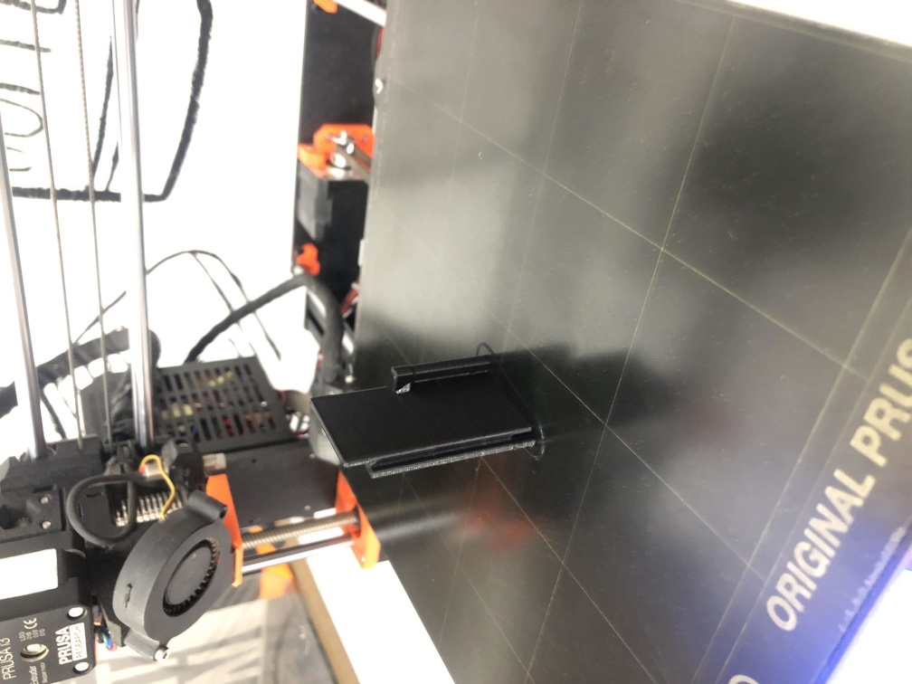
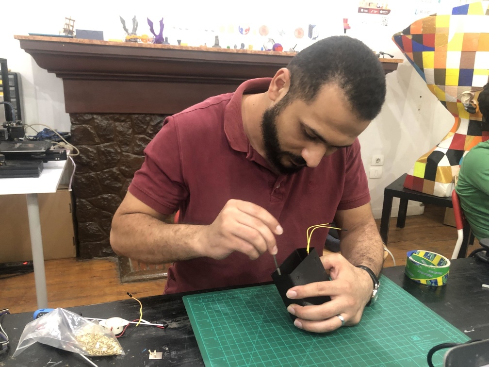
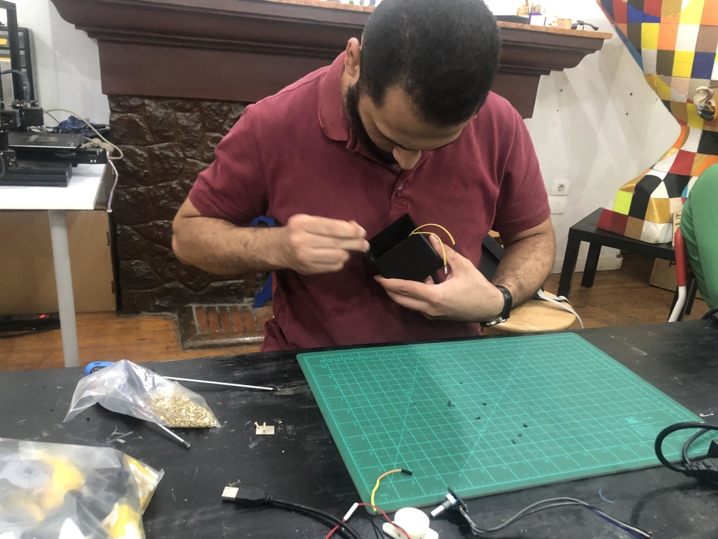
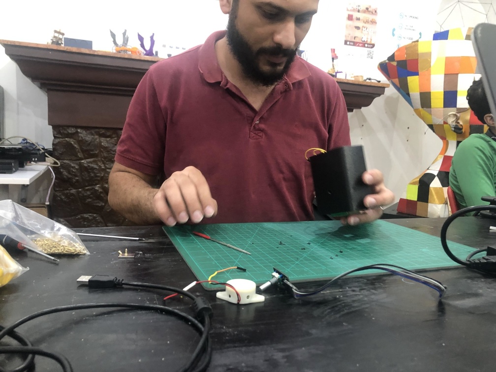
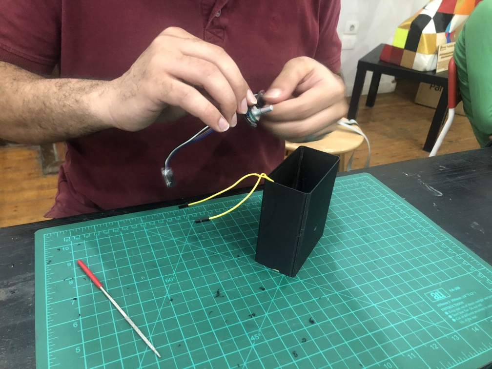
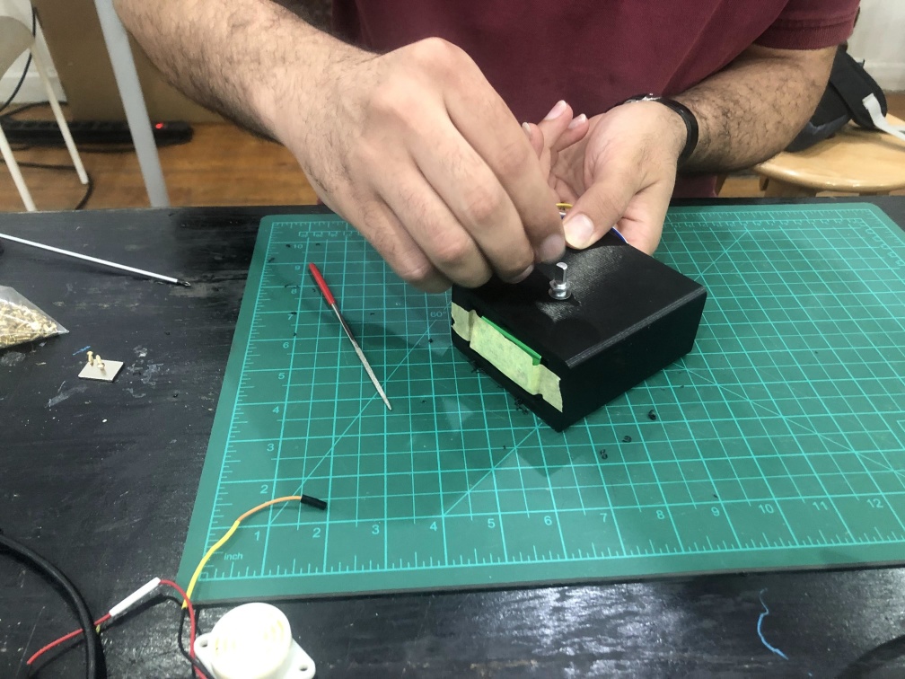
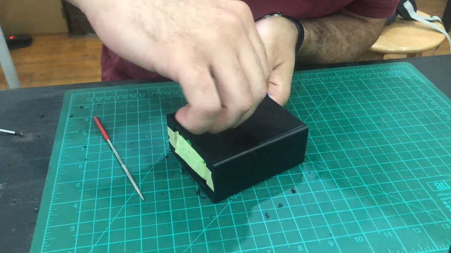
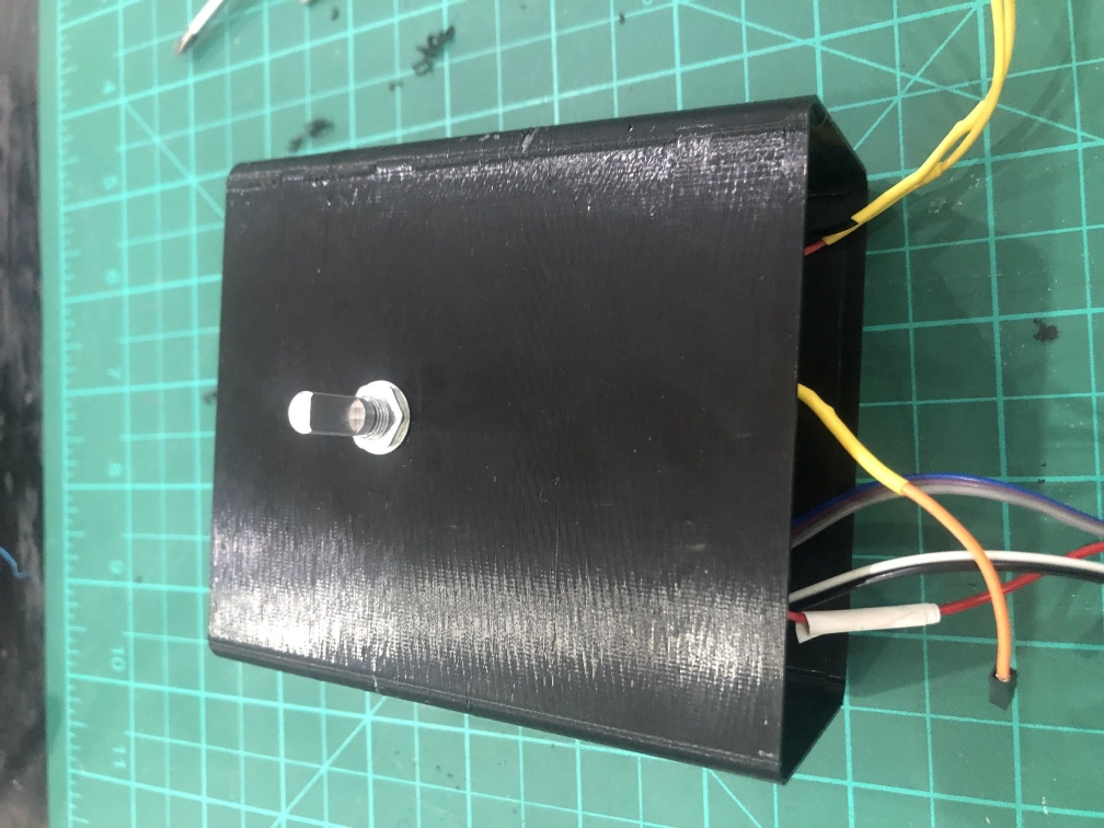
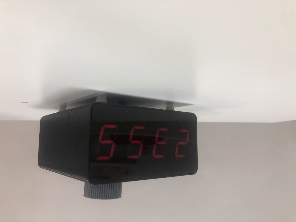
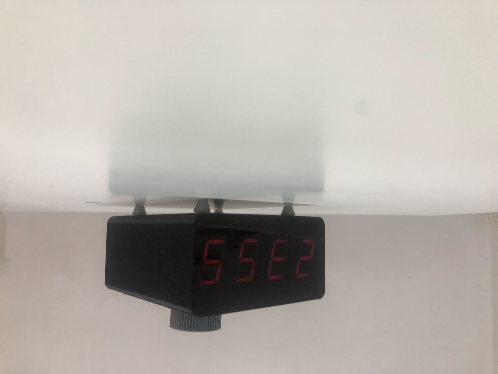
3D design
- for 3D desing I use Solidworks.
- Desing consists of 2D acrylic piece that is in the front and I used a laser cutting machine to make it.
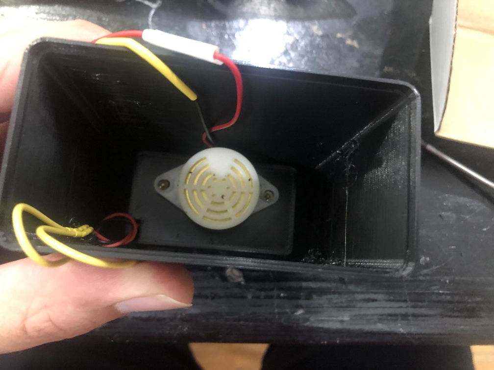
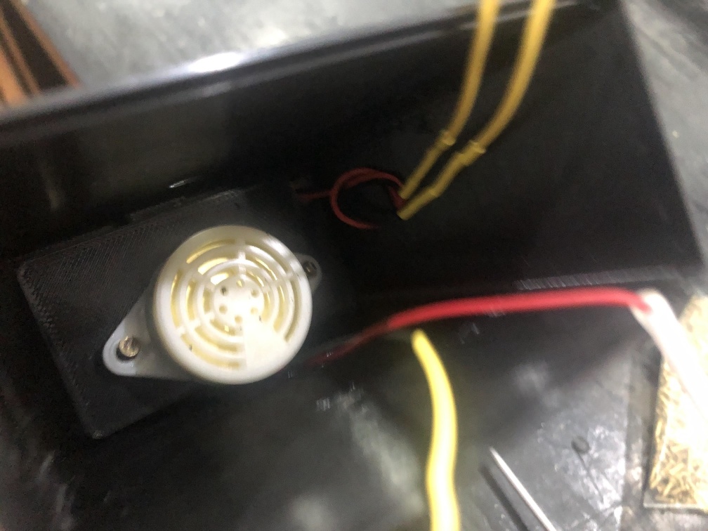
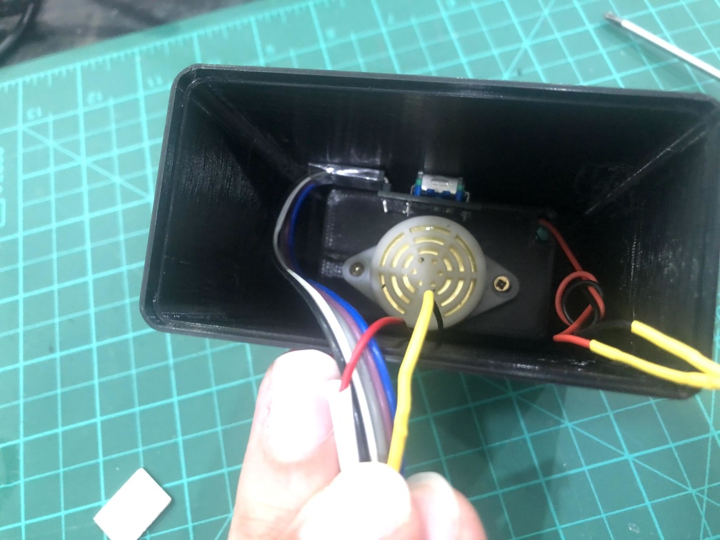
- The enclosure is 3D printed and it cosists of battery housing, speaker fixtures, encoder fixture and encoder knop.
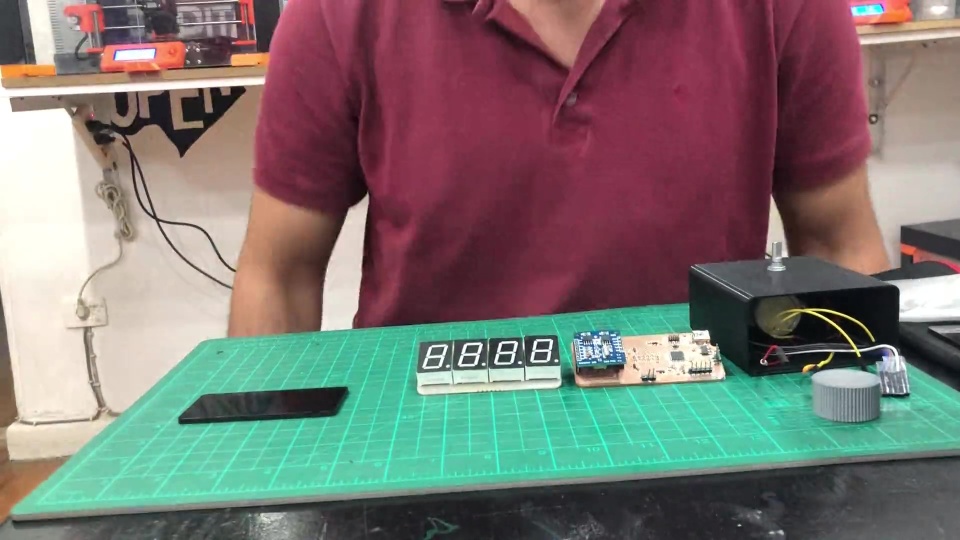
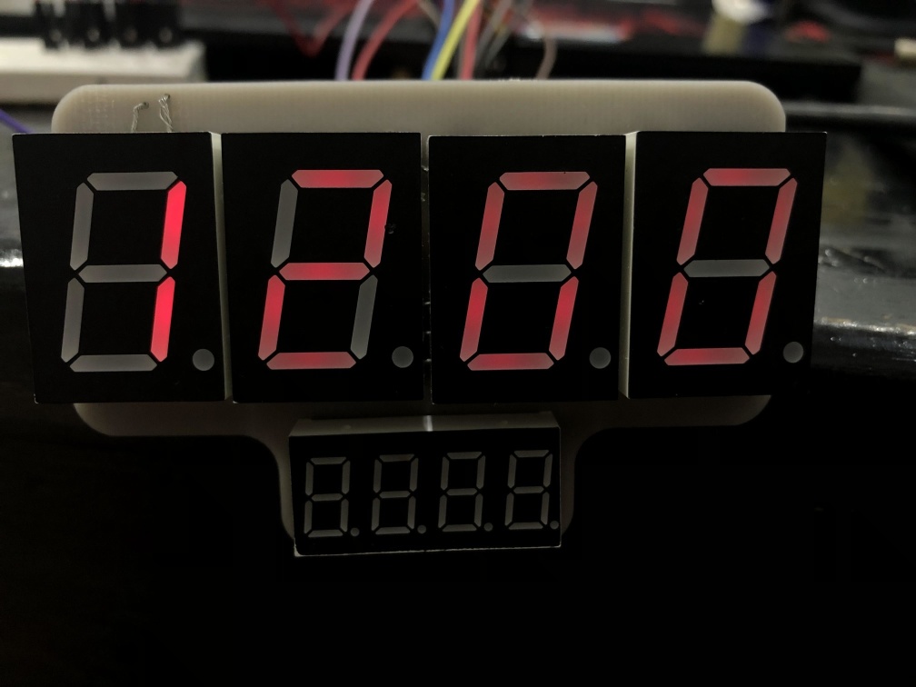
Output
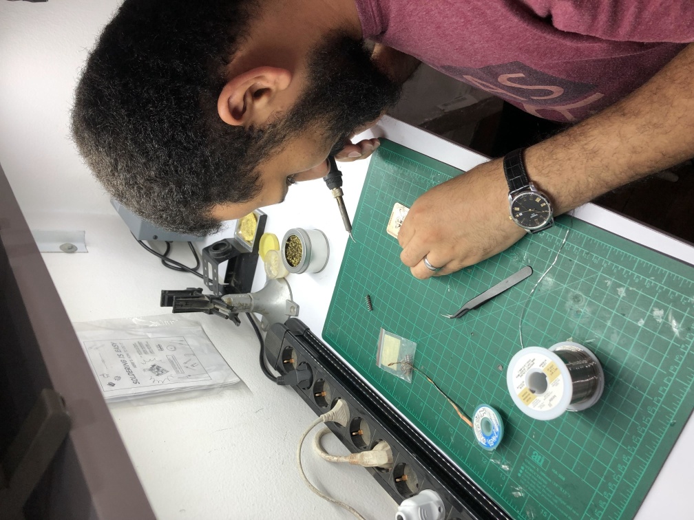
After Assembling all components together and uploading the final code to the board, it worked fine, here's some hero shots and final presentation slide and video.
Smart Clock by Omar Seif El Eslam is marked with CC0 1.0![]()
![]()
Downloads
KiCad project for 7 Segments PCB Design KiCad project for main SamD21E17 PCB Design Code Enclosure design in solidworks 2021Aknowledge:
- I want to thank my instructors Mohammed Kamel, Noha Hani, Ahmed Saeed who helped me alot during the journey of Fab Academy, they didn't help just in technical but also in many other ways I believe without them I would be wasting alot of time.
- Thanks to Amany, Omar and Moiz my colleuges in this round of Fab Academy, they were nice, helpfull kind and all the good attributes you can think of.